The serial port is available on almost all PCs. Even the most recent ones tend to have at least one of these ports, even though this has been derided as "legacy", a synonym of "obsolescent" for a while now, by some manufacturers who would like to push their own semi-closed standards and maybe save the money for a connector. This may apply to a narrow PCompatible standard, but look at some slightly older hardware of workstation or minicomputer origins, and the serial port is one of the few kinds of connections that they will all have, and that can be expected to be electrically and software compatible.
On PCs, there are two main plug variations, DE9M and DB25M, to contend with. Some multi-serial cards may use DC37 male or female, but they also provide an "octopus" cable with standard male, usually DB25, connectors. Various other kinds of female D connectors on PCs can be expected to be for other things: DC37Fs can be for extra floppy disks or some kinds of technical interface card; DB25F are probably paralell ports, occasionally SCSI ports or even IEEE-488, DA15F can be for joysticks, high-resolution monitors or ancient-style thicknet-MAU network connections. DE9F were usually for old CGA, EGA, or monochrome IBM monitors. High-density D connectors, most often DE15 (with 15 pins in three rows, in a shell the same size as the 9-pin DE9) are usually for monitors.
The following pictures show some of the variety:
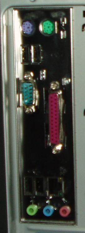
This is the backplane of an ATX-format system of recent vintage. There seems to have been some kind of color-coding effort to identify the standard ports on recent hardware. The various connectors' bodies have distinct and peculiar colors which sometimes also appear on the molded plugs on various cables. Thus, serial ports are cyan, printer ports are purple, and game ports are yellow. Other ports that do not use D connectors are also colored, thus, mouse ports are green, keyboard ports are violet, and sound card plugs are pastel blue, red, and green. Of all these, usually only the serial ports and the power inlet are male.
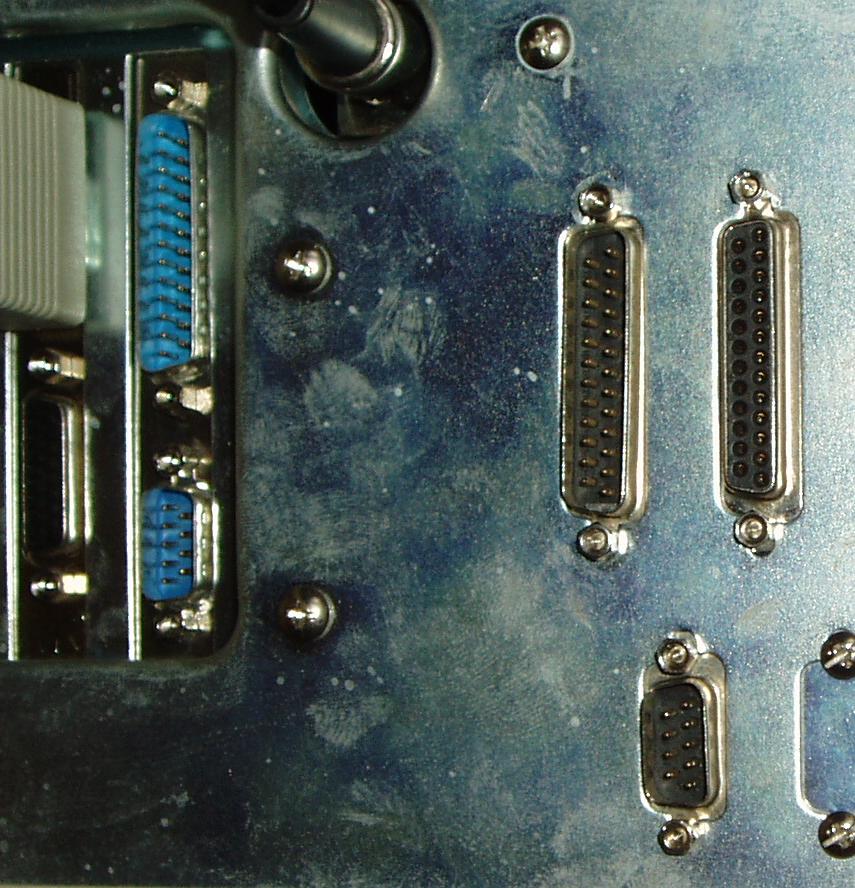
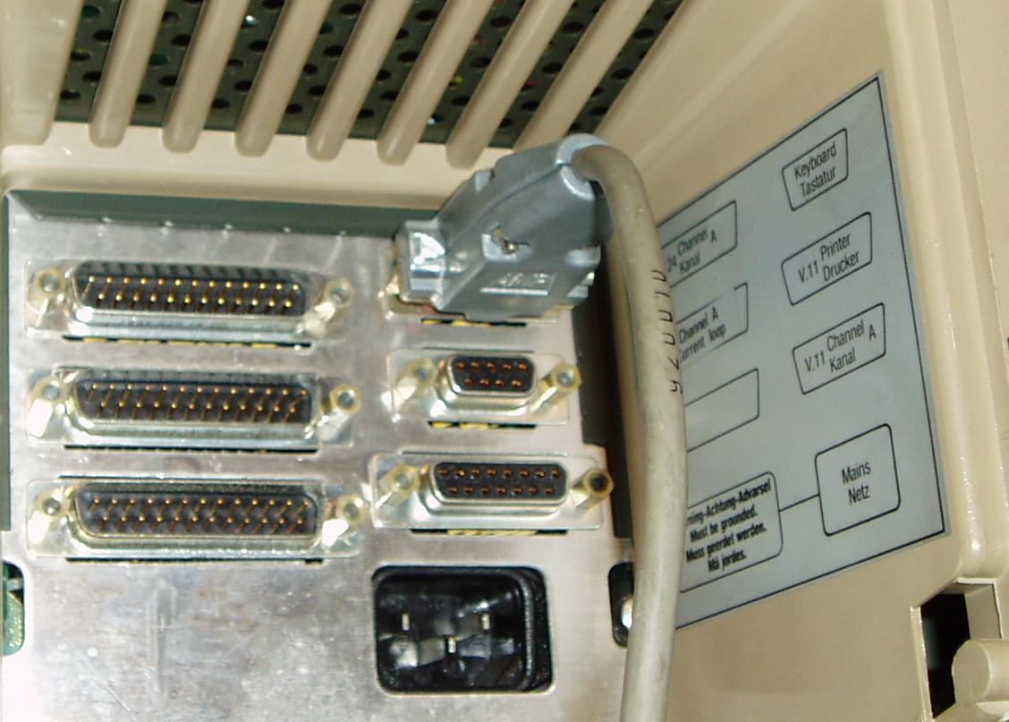
This shows some of the connectors on an older PC. Here are 4 serial ports and one parallell port. These can be clearly identified by the male or female connectors: the female on the right is the parallell port. We also can see parts of the keyboard connector and the monitor cable. The connector beside the one where that cable is plugged in, which is the same outside shape as a DA15, actually has 3 rows, and is for some other kind of monitor plug.
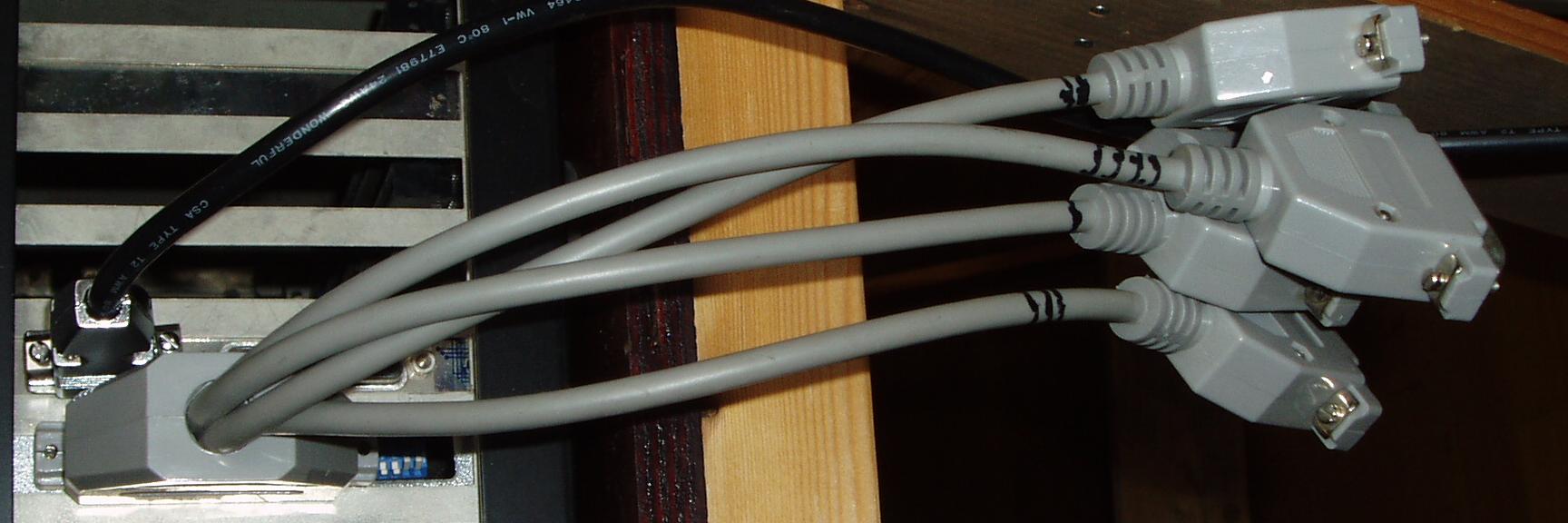
This is an "octopus" cable for 4 serial ports, connected to a DC37. Each cable ends in a DB25M.
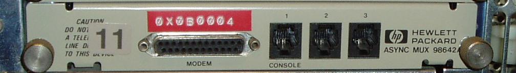
This is the backplane of the HP98642A. Three ports are 4-way RJ11, where the pins are:
| RJ11 | DB25M | Code | |
| 1 | 2 | TxD | Transmitted Data output |
| 2 | 7 | GND | Data Common |
| 3 | - | +5V | HP docs indicate this is not used. |
| 4 | 3 | RxD | Received Data Input |
The Pin 3 carries 5V, and inspection of the card reveals this pin is connected to the main 5V bus in the machine. It appears to be useable for powering some smaller units or interface kits, but any noise voltages introduced here, or even worse, short circuits or overloads, could have a bad impact on the rest of the computer, so the official "Not Used" might be worth remembering. It might also have become completely disconnected in a later revision, for a very good reason. You see, the pinout for the common phone line is pins 2 and 3 above.
Now, from the warning ("DO NOT CONNECT A TELEPHONE LINE DIRECTLY TO THIS DEVICE") partially obscured by the label "11" for the select code, I wonder how many of these units fell prey to someone forgetting the modem and plugging one of the ports 1 to 3 straight into a phone line, and then being surprised by the computer shutting down perhaps permanently when the phone rings and 86V AC is impressed across the +5V power supply!
Of course, they should pay attention to the legend MODEM and realize that an RJ11 plug doesn't readily mate with a DB25F. This kit was made to last, during a time it was expected that it was tended to by people with a clue. Considering the rest of the backplane with its variety of connectors for SCSI, IEEE-488, monitor, ethernet, speaker and keyboard, It can be a right magpie's nest of cables back there when everything is up and running.
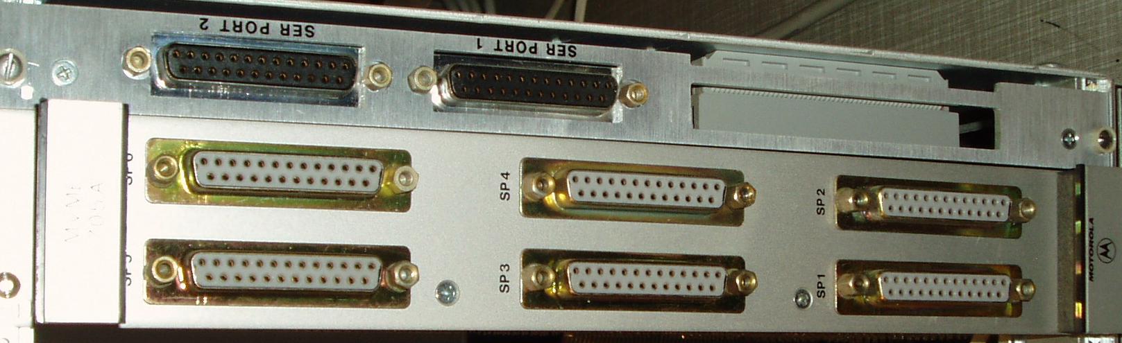
This is part of the backplane of an MVME131XT system showing 8 serial ports, all female DB25. These can be set to either DCE or DTE by moving around jumpers inside.
There are many to choose from here. Fortunately, there is a legend posted on the inside right wall of the niche in the back of the unit, and as can be seen from that, the RS-232 that we are interested in is the male DB25 at the top left in the picture. V24 is another term which corresponds to what we call RS-232. I suspect the connector at the bottom left is unused, or it is a spare for some optional additional interface that was never included in this particular model. One day, I'll open up the unit and see what is inside.
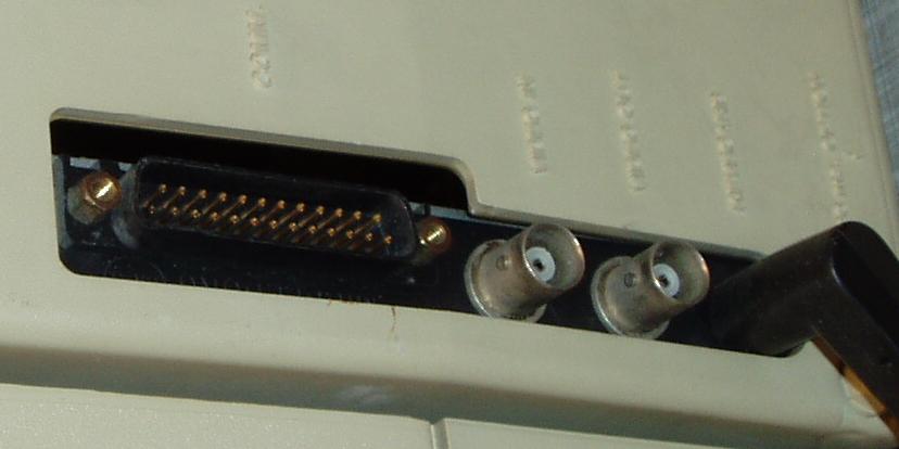
The VT100 has just the single male DB25 labeled "COMM". There are also some video ouputs on the BNC connectors below.
Other computers and terminals frequently have the DB25 connectors, though they might sometimes be female, and note that other varieties exist, like the RJ11 jacks on the HP98642A. Fortunately they are usually marked, or there is some kind of documentation available identifying them.
Besides the matter of the connector itself, there are two different main electrical connection schemes, known as DTE (Data Terminal Equipment) and DCE (Data Communications Equipment). The DTE has 5 outputs and 3 inputs, these match the 5 outputs and the 3 inputs of the DCE.
In certain cases, only a subset of these 8 signals may be present, down to the minimum of 2: Data in either direction, which is what the 4-terminal RJ11 sockets on the HP98642A offer. The connectors can still be wired as per DCE or DTE however.
RS-232 specifies that the male connectors (such as the ones on the PC) should be on DTEs and female connectors (such as the ones on modems) should be on DCEs. The computer-modem connection was the original purpose of this standard. Because of the electrical simplicity of few wires, this has become popular for connecting anything to anything else as well.
Many older machines may have jumpers inside for configuring their ports as either DCE or DTE. Newer PCs seem to be DTE only with male connectors, newer peripherals such as modems have a DCE wiring and a female connector; and this is in keeping with the sex of the connector as specified by the RS-232 standard.
Other machines and equipment may have DCE or DTE pinout and male or female connectors, and any of the 4 possible combinations (male-DTE, male-DCE, female-DTE, or female-DCE) may be found. The ones shown as D-connectors in the pictures are all of the DTE pinout, whether male or female.
The idea behind the standard male-DTE and female-DCE is that all wires will match pin for pin, and all cables will be identical and have a male and female connector at either end, and may be connected in sequence, just like ordinary power extension cords.
For the DTE male plugs seen on most PCs and the DTE female connectors seen on other computers:
| DE9M | DB25M | Code | Official Name | Direction |
| 1 | 8 | CD | Carrier Detect | Input from DCE |
| 2 | 3 | RxD | Received Data | Input from DCE |
| 3 | 2 | TxD | Transmitted Data | Output to DCE ("Two Terminal Transmit") |
| 4 | 20 | DTR | Data Terminal Ready | Output to DCE |
| 5 | 7 | SG | Signal ground | Reference ground |
| 6 | 6 | DSR | Data Set Ready | Input from DCE |
| 7 | 4 | RTS | Request to send | Output to DCE |
| 8 | 5 | CTS | Clear to send | Input from DCE |
| 9 | 22 | RI | Ring Indicator | Input from DCE |
All these 9 lines are used for modems. However, not all lines need to be used for interfacing projects, and some of these may serve as additional inputs or outputs, independent of their original purpose. Also, we note that not all of the 25 pins are needed; and for some reason the pin numbers between the two do not seem to have been preserved even though this could have been nearly perfectly possible with at least pins 2-8 all the same. In particular note the big gotcha! coming from the interchange of pins 2 and 3.
There are two general output bits and four general input bits available, and one may even have interrupts issued on changes in these inputs. The following tables show these signals, and the 8250, 16450, or 16550 UART control (+4) and status (+6) register bits, as well as the Linux ioctl(2) flag names.
The two output bits are RTS and DTR:
| Name | Pin | Pin | UART +4 | ioctl(TIOCMGET/TIOCMSET) |
| RTS | 4/25 | 7/9 | Bit 1 | TIOCM_RTS |
| DTR | 20/25 | 4/9 | Bit 0 | TIOCM_DTR |
The four input bits are CD, RI, DSR, and CTS:
| Name | Pin | Pin | UART +6 | ioctl(TIOCMGET) |
| CD | 8/25 | 1/9 | Bit 7 | TIOCM_CAR |
| RI | 22/25 | 9/9 | Bit 6 | TIOCM_RNG |
| DSR | 6/25 | 6/9 | Bit 5 | TIOCM_DSR |
| CTS | 5/25 | 8/9 | Bit 4 | TIOCM_CTS |
For all of these, 1 or bit set corresponds to a Space, and 0 or the bit reset corresponds to a Mark. (See section 2 for the meanings of Mark and Space). For the Linux device drivers discussed in section 10, the convention of the ioctl(2) flags also tends to be set or 1 for Space and clear or 0 for Mark.
Obviously, if the data channels are used at the same time, the coding for this could become rather complicated, but at least this is possible. Also, on a DOS shell under NT4, it seems we need to wiggle the DTR and RTS a little bit initially before they obey.
For simple interfaces between 2 PCs or a PC and another DTE-wired device, as well as Laplink and Debug connections, a simple 3-core cable with a (female) DE9F or DB25F at either end, for the minimum of connections will do:
| DE9F | DB25F | DB25F | DE9F | |
| 3 | 2 | >>> | 3 | 2 |
| 2 | 3 | <<< | 2 | 3 |
| 5 | 7 | --- | 5 | 7 |
The same applies for male-male cables. Thru cables with a male and a female connector either end will have pins 2 and 3 the same if their sizes are the same and 2 and 3 crossed if one is a DB25 and the other is DE9. All DB25s have common on pin 7 and all DE9s have it on pin 5. A complete table for all these varieties which result in all male plugs being DTE and all females being DCE:
| One end | Other end | |||||||||||||||||||||||||||||||||||||
|
|
|
I have had great success using UK 3-core 0.5mm2 mains cable; these are rugged while still flexible enough.