From a message I got from the user "stark", via the Hacking WD MyBook World Ed forum, I wrote a summary on how I had got the I2C-bus working, both hardware and software, and how I made the bus extend outside the cabinet of tbe WD Book World.
The example shown will be for a DS1621 running at 5 V possibly at some distance external to the disk unit. This entails making a voltage-level translator, which also serves to protect the WD Worldbook from accidental wrong connections that are easy to make during experimentation.
The I2C-bus inside the Worldbook, like the rest of the internal circuitry, runs at a system voltage of 3.3V. There is a power-supply available at the serial-port connector, J4, pin 1. The rest of the serial-port connections are as follows (as per http://www.galmiche.com/mybook/a).
| J4 pin | Function |
| 1 | 3.3V |
| 2 | GND |
| 3 | Serial Data into the WDbook |
| 4 | Serial Data out from WDbook |
Then there is the position U9, where the M41RT00 could have been but isn't, in my disks.
| U9 pin | Function |
| 4 | GND |
| 5 | SDA |
| 6 | SCL |
See the page A Second Look for the details on how I figured this out. Even if the chip were in place, we could still use the I2C bus.
We will in any case have to keep away from the bus address that this chip uses, 0x68, either because it is there and occupies it, or in all cases, the operating system expects there to be one at this address. If we have something else there instead, funny things might happen.
So no using bus address 0x68.
Now, I don't know how much current the power outlet at J4 pins 1 and 2 can supply, and what kind of damage can result from short-circuiting this. Certainly, the power available will be enough to run a 3232 serial level converter chip, and the 1 mA or so that a single DS1621 requires is also likely within budget -- after all, I've connected one, and it worked, and the disk unit has survived -- but I would not want to depend too much on the absence of an accidental short circuit, which otherwise could burn out the regulator and whatever else. At the very least, the disk controller would have to be re-started.
The RS232 serial port robustness as a 3232 provides is nice: it can be connected and disconnected with power on either side -- as it turns out, there is a way of connecting the I2C bus lines in an equivalent manner, allowing connecting and disconnecting external devices (with some care!) without having to power down the WD Book.
Philips, has an application note where this is discussed. It is a matter of connecting two NMOS transistors between two I2C-busses that can be of different system voltage. Additionally, one of the busses can be powered down independent of the other, so that devices on the powered-down side can be connected and disconnected, without affecting the devices on the powered-up side. So we have 3.3V on the inside and 5V on the outside, for example. This is suitable for a shorter distance on the outside, say a couple meters, if we want to go further, we can use something like the P82B715 extender circuits.
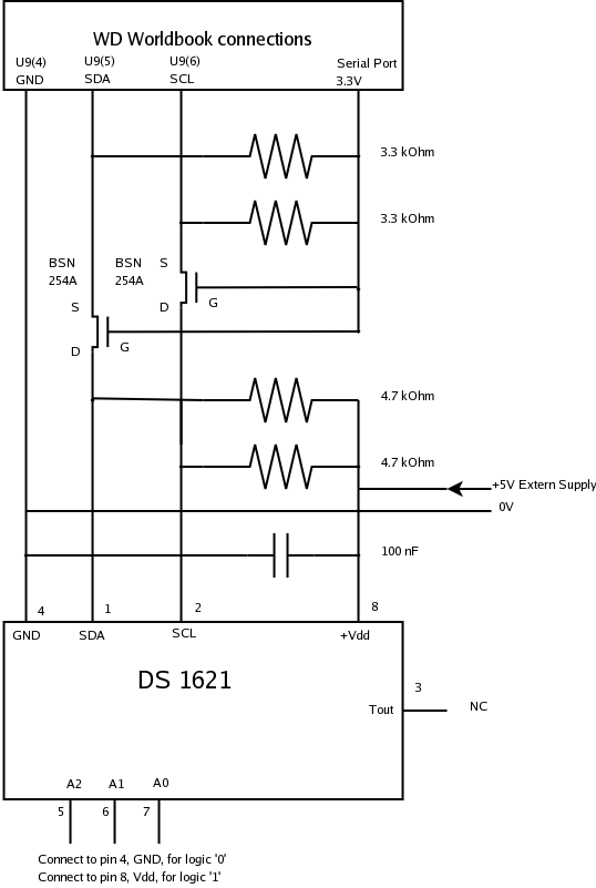
I made this buffer stage with BSN254A, and four resistors, 3.3 kOhms on the 3.3V side and 4.7 kOhms on the 5V side. The BSN254A N-channel MOSFETs have the suitable threshold voltage, around 1.8V for use at 3.3V. Note that the 2N7000 will not work at this low voltage.
I put the level translator circuit on a board, together with a 3232 serial-level translator, and put this inside the cabinet. Just above the disk itself, there is what seems to be mounting posts, and I used these to put my circuit board on. I also used a 2 by 6 angled pin-header going through a cut-out slot in the top wall of the case, for connecting the external cables. I used thin wires, originally meant to be used for wire-wrapping, to attach my circuit board to the U9 and J4 positions on the system circuit board.
There are 4 external connections for the I2C bus: 0V, SDA, SCL, and the +5V externally supplied. No need to extend the internal 3.3V and thus a greatly reduced risk of damaging it as well.
The DS1621 is a temperature-sensor, with I2C interface, and with a thermostat output, that can be used to control an external heater or chiller via a relay. It provides temperature readings with 0.5 degree C resolution, and with a programming trick, can give us 0.0625 degree C resolution.
It comes in an 8-pin package, I have used the DIP (Dual In line Package) version, as the surface mount ones are harder to work with. These have a smaller thermal mass however, so they may be preferrable in some cases.
It also deals with both one- and two- byte commands and data, so it gives good examples of how to handle these in software. This is in contrast to serial EEPROMS, which have all addresses the same length. And who needs an EEPROM connected to a disk storage unit anyways?
The package's 8 pins are assigned as follows:
| pin | Name | Function |
| 1 | SDA | I2C Data |
| 2 | SCL | I2C Clock |
| 3 | Tout | Thermostat output |
| 4 | GND | Ground, 0V |
| 5 | A2 | Bus Address Selection Bit 2 |
| 6 | A1 | Bus Address Selection Bit 1 |
| 7 | A0 | Bus Address Selection Bit 0 |
| 8 | VDD | Power, 2.7 to 5.5 V |
The DS1621 can be assigned at bus addresses from 0x48 to 0x4F, (1001xxx), and the last three bits are defined by connecting the A2, A1, and A0 pins to VDD for a 1 and GND for a 0. Thus, as many as 8 of these can be paralleled on a single I2C bus, connecting all the SDA and SCL pins together and making sure all of them have different connections to A2,A1, and A0.
Other I2C-chips may have other address selection schemes, though the 4 fixed and 3 selectable bits seems to be quite common. The PCF8591 A-D and D-A converter uses the same bus addresses, (0x48-0x4F or 1001xxx) while the PCF8574 parallel IO circuit goes into the range 0x20-0x27 (0100xxx). The maximum is thus limited in part by the bus addresses, and in part by the capacitance of all the paralleled SDA and SCL inputs.
The following shows the connection diagram, linking the WD Book and the DS1621 circuit with the MOSFETs in the level translator circuit.
On the software side, the controller has some, but not all, relevant modules loaded. There is one of them missing, and the device-file might not be present. These are easy to establish however, and the operating system can be configured to have these turned on at boot.
To make the software work, there has to be a device file, /dev/i2c-0, as supported by the kernel module i2c-dev. Then the device-file has to have the correct permissions so that a non-root process can access it.
Logged in as root, first check the presence of the kernel module:
root# grep i2c /proc/devices
    89 i2c
If there is an i2c device listed in /proc/devices, the module is in place. If this entry is missing, the i2c-dev module should be loaded:
root# modprobe i2c-dev
Now see if the i2c has shown up in /proc/devices. To make this happen automatically on start-up, insert the following line
::sysinit:/sbin/modprobe i2c-dev
into /etc/inittab, somewhere after the line which refers to /sbin/modprobe i2c-oxnas-bitbash, This additional line has the same general syntax, just that is refers to i2c-dev instead.
Having the module loaded, check for the presence of /dev/i2c-0, which has major number 89 and minor number 0:
root# ls -l /dev/i2c-0
crw-rw-rw- 1 root root 89, 0 Oct  8 12:57 /dev/i2c-0
If it is missing, create it with mknod and set permissions to 0666 (everyone can read and write):
root# mknod /dev/i2c-0 0 c 89 0
root# chmod 666 /dev/i2c-0
root# ls -l /dev/i2c-0
crw-rw-rw- 1 root root 89, 0 Oct  8 12:57 /dev/i2c-0
Once created, the device-file will remain in the system past booting.
This example program shows how to talk with the DS1621 on the I2C bus. The device file is not dependent on the particular I2C-capable device connected, and we can have a number of DS1621s and PCF8574s and whatever else sitting at different bus-addresses, and use functions such as:
to communicate with them. For the DS1621 here, it is expected to be at address 0x48 (A2, A1, A0 all connected to GND). See the DS1621 datasheet for the meanings of the parameters to these function calls. Such parameters will be different from each chip to the next. For example, the MCB8501 is another thermometer circuit, externally very similar to the DS1621 (8 pins, same function on each pin as the DS1621) and even its bus-addresses go into the same range, but its programming commands are very different.
/* ds1621 higher resolution using counter info. */

#include <stdio.h>
#include <string.h>
#include <stdlib.h>
#include <unistd.h>
#include <fcntl.h>
#include <linux/i2c-dev.h>

/* open i2c
        set 1-shot
        start measurement
        wait until meas done
        Read Tm
        Read counter
        Read slope
        close i2c
        calculate hi-res temperature value from these
        print the value
*/
int main(int argc, char **argv)
{
        char i2cdev[128];
        int ba;
        int sb, fd, done;
        unsigned int s, t16, tf, co, sl;
        int t8, t9;
        double thr, tlr, dco, dsl;

        strcpy(i2cdev, "/dev/i2c-0");
        ba = 0;

        fd = open(i2cdev, O_RDWR);
        if(fd < 0) return(1);

        /* The I2C device is opened, then the device of interest on the bus is selected with
            the ioctl(I2C_SLAVE) call. All subsequent reads and writes will refer to this
            device, until another ioctl(I2C_SLAVE) call is made to change the selection */

        sb = ioctl(fd, I2C_SLAVE, 0x048 + ba);  /* 1001000 */
        if(sb != 0)
        {
                close(fd);
                return(2);
        }

        /* Set 1-shot mode, reset the gate-flags. */
        /*  0  = dont care
            0  = reset THF
            0  = reset TLF
            0  = don't care
            1  = reserved
            0  = reserved
            1  = Output active H
            1  = Sets 1-shot mode */

        i2c_smbus_write_byte_data(fd, 0x0AC, 0x0B);

        /* Start conversion */
        i2c_smbus_write_byte(fd, 0xEE);

        /* Wait for the conversion to be done. Can take a second or so */
        do
        {
                sb = i2c_smbus_read_byte_data(fd, 0xAC);
               done = (sb & 0x80);
         }
        while(!done);

        /* Read  */
        s = i2c_smbus_read_word_data(fd, 0xAA);
        t8 = (s & 0xFF);
        if(t8 & 0x80) t8 |= ~0xFF;
        t9 = (t8 << 1) | (s & 0x8000 ? 1 : 0);
        tlr = (double) t9 / 2.0;

        /* Read the counter and slope */
        co = i2c_smbus_read_byte_data(fd, 0xA8);
        dco = (double) co;
        sl = i2c_smbus_read_byte_data(fd, 0xA9);
        dsl = (double) sl;

        thr = (double) t8 - 0.25 + (dsl - dco) / dsl;

        printf("LO-res T = %G\n", tlr);
        printf("HI-res T = %G\n", thr);

       close(fd);
       return(0);
}
This is compiled with a regular command, if the above code is in ds1621hi.c, something like
cc -O -o ds1621hi ds1621hi.c
I found out that the compiler requires the -O (capital oh, for optimizing off) command. If this is not passed, the program does not really do the various i2c_smbus_...() functions, since the compiler has optimized them away. All that happens is that the apparent function calls returns 0 and ok on everything. Had me wondering for a while when hooking up the I2C on a second Worldbook, with the slightly more recent firmware in it, and nothing seemed to happen.
The original, "blue rings", version of the WD Book World seems to have been discontinued. Possibly because there were software bugs, in particular the version 2 ones were in need of some TLC just to work right at all. There appears to be a newer model out, the "white stripe" ones, with an updated controller and completely new kernel. They still have a serial port, from what it looks like on the forum, but I have no idea if there still is any I2C bus in them. I'd have to get one and open it up to find that out. However, if there is one, the electrical and software interfacing will be very similar to what is shown here.
I have had great success with this I2C level-shifting and isolating circuit using other 3.3V devices, notably the Picotuxes, which also have an undocumented I2C interface.
Go back to Western Digital MyBook World Edition index page
Skip back to Initial observations
Go back to A Second Look
Go up to the index page