Here are more details on the unit on the living room wall. Its purpose is to measure and display the room temperature, and to allow for setting a desired temperature.
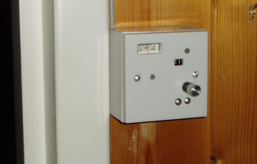
This is the external view. As can bee seen, there is a little moving-coil meter indicating the actual temperature, a window where the set temperature in degrees, 21 in this picture, is shown, and a knob with which one may set this desired temperature. The unit communicates with the main controller sitting in the boiler room through a 4-core screened cable, which we can see emerging upwards at the top left corner, along the door jamb.
Here is the internal view of the unit. On the left we see the back of the mechanical digital display. You can se the 42-tooth gear on the potentiometer shaft, the 14-tooth one on the side of the counter dials above this, and the worm drive coming from the front knob, just below. The counting mechanism consists of two of the digit wheels from an odometer.
We also see the circuit board and the back of the moving coil meter. This was taken from a defunct radio-cassette player. A large black capacitor is connected across the meter terminals, this can be seen on the top center of the picture.
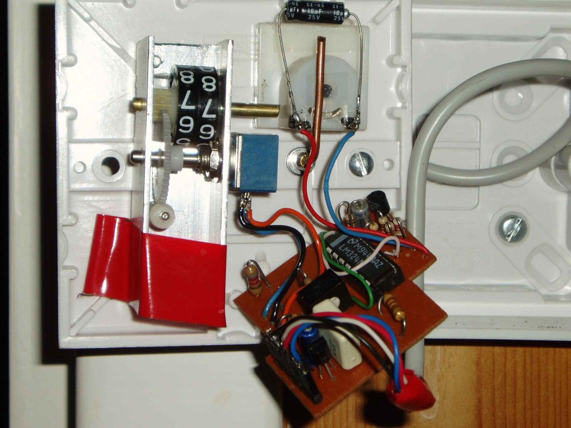
The LM35 sensor which actually measures the inside temperature is the black component seen at the far corner of the cicuit board, above the LM324 IC, behind the resistors. The markings on these two ICs are visible at large resolutions. The 3-terminal voltage regulator is visible near the cable entry plinth in the near corner, next to a large white capacitor.
Here is the circuit-diagram of this unit, where the connections and some key voltages are shown. Most of the components, except for the potentiometer, the moving-coil meter and the large capacitor across the meter are on the circuit board.
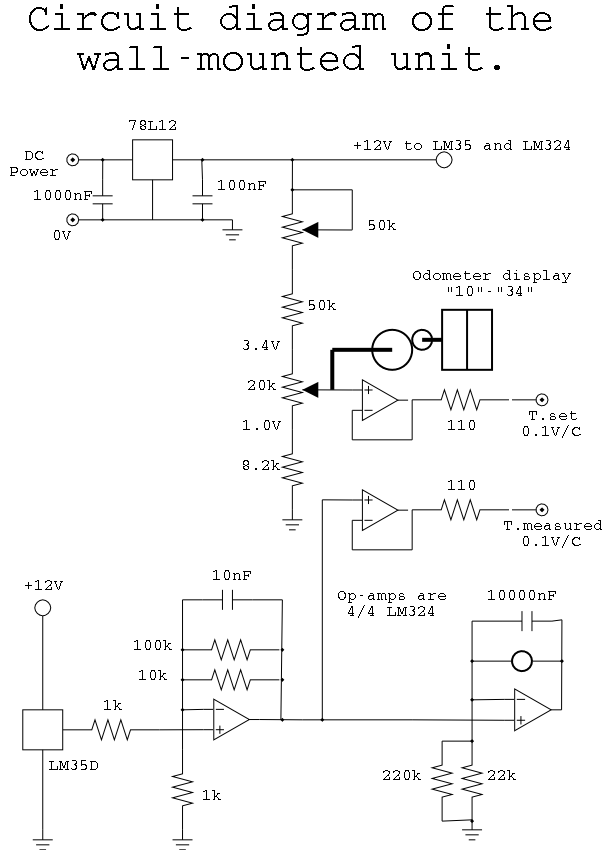
The power fed to this unit is 15V DC, and it is regulated down to 12V DC by the 78L12 voltage regulator
The four cores in the cable carry the power, the set temperature signal, the measured temperature signal, and the power and signal returns. The LM324 amplifiers boosts the 10 mV/C signal from the LM35 to 100 mV/C, and it also serves to generate a similar scale factor from the potentiometer. The component values are chosen so that the voltage on the set temperature line is directly related to the value shown on the odometer in the front window, at 100mV/C.