Here are more internal details of the stand-alone outside temperature measuring unit.
On the inside view of this display unit, the three connectors for the sensor, the serial port and the 9V AC power, are visible:
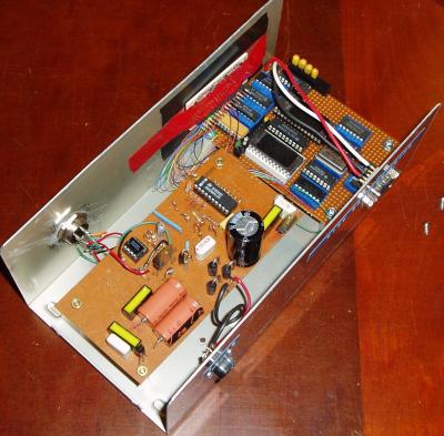
We can see the back of the display on the inside of the front panel, and we also see the analog parts on the PCB to the left, where the wires go from the sensor input connector through an op-amp and onwards to the A-D converter (an ADC0804LCN), the 20-pin IC near the middle of the box.
The rest of the components are the 5V supply for the digital circuits, the -5V supply for biasing the LM35 so it generates negative voltages in the cold, and the +5.12V supply for the ADC, for a nice, even 0.4 C/unit resolution. The signal is level-shifted by the resistors visible just below the ADC0804.
The chips on the wire-wrap board beside it form the digital parts. The EPROM in the white socket is a 2716 which controls the display, and the other EPROM partially obscured by the three fat wires for the serial port generates the bits to go out there. The four yellow capacitors on the rear edge of the board are used by the the MAX-220 TTL-to-RS232 signal converter. The serial port connection is the usual D9 male connector using 3 wires. Any input signal will cause a counter to reset and then run through 64 addresses of the EPROM where all the signals for the serial port for the current temperature output is stored.
This unit is completely independent of the temperature controller in the boiler room, their only common connection is the data-logging PC, named "hawthorne" after a character of the Sherman's Lagoon comic strip. I did not see any point in taking a picture of that, it just looks like an ordinary desktop computer, which is just what it is.
Here are some circuit diagrams of the outside temperature unit.
Diagram 1/4 shows the connections for the outside sensor and the analog circuitry before the A-D converter. The negative bias causes the LM35 to generate negative voltages in the cold, 0.01V/C. The amplifier stage makes this into 0.1V/C and the subsequent level shifter compresses the voltage range from -5V to +5V (for -50C to +50C) into the 0-5.12V range of the ADC0804 A-D Converter.
The inversion shown on data line A7 provides 2's complement readout for the display and serial transmitter PROMs. The choice of 5.12V for the ADC gives us a step size of 40 mV corresponding to 0.4 degrees C.
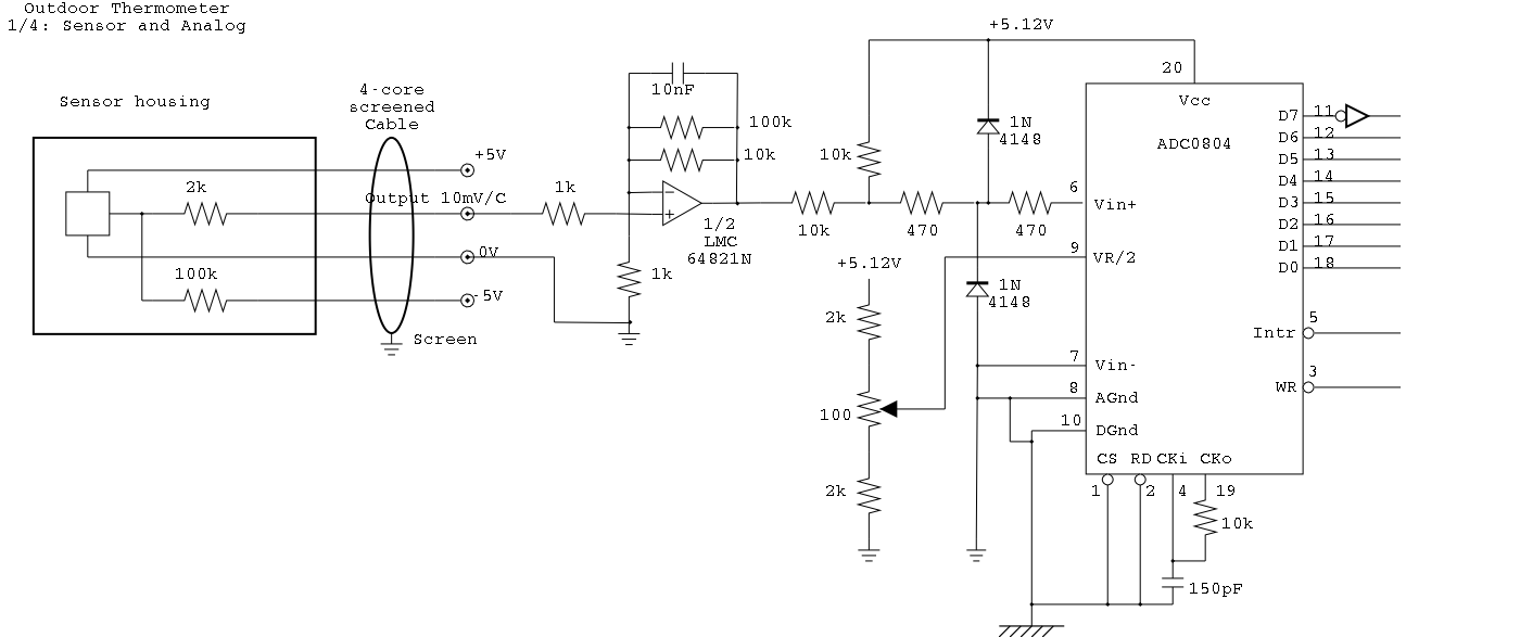
Diagram 2/4 shows the power supplies. There are 3 of these: a 5.12V one for the analog circuits, a -5V one for biasing the LM35 and the negative supply for the op-amp, and a 5V high-current supply for the digital circuits, which are a mix of TTL and CMOS.
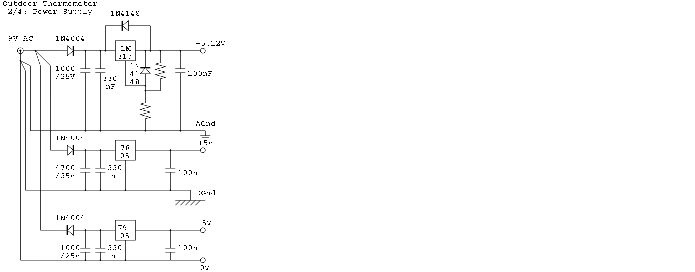
Diagram 3/4 shows the display-unit. There is a 2716 PROM which contains the bitmaps of the various figures, 8 of its address lines are driven from the ADC0804, and two address lines are driven from the display counter (the 74LS74 at the far right). The data output lines are buffered in a 74LS244, then this drives the anodes of the 7-segment display, including the decimal point. The cathodes K1 to K4 are driven from 7438 NAND buffer gates, and scanned at a rate of 512 Hz.
Every 1/2 second or so, the ADC makes another measurement and the display is updated.
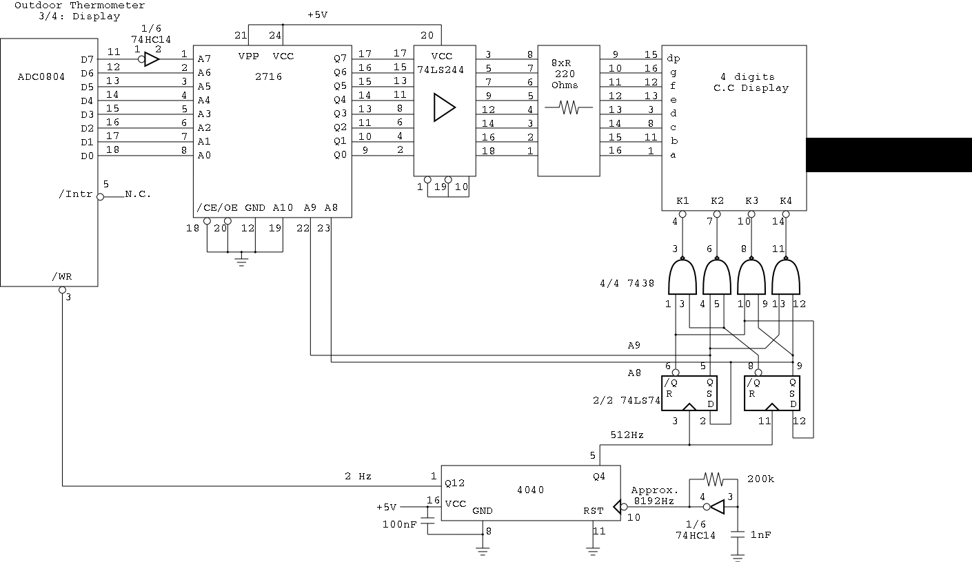
Diagram 4/4 shows the serial transmitter. Somewhat similar to the display, the bit patterns are stored in an EPROM, using 8 of the address lines as data input from the ADC, and the signal comes out on the data output line.
This time, 6 address lines (A8 to A13) select one of 64 "chips" of the output, and these are organized so that the bit patterns corresponding to 5 characters, including start and stop bits, are emitted.
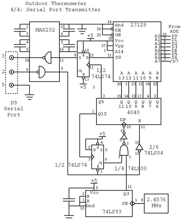
When any character is sent to the device, on the serial line coming in, the 4040 counter is reset, and starts counting at a rate of 307.2 kHz (The 2.4576 MHz oscillator rate divided by 8 in the 74LS93). The 6 bits from the counter selects sequentially 64 of the bytes in the 27128 EPROM, and bit 0 from each of these is transmitted, through the latch and the MAX232. When the 4040 has counted past these 64 bits, the counter's Q12 goes H; this stops the counter, so it is ready for the next reset.
50 out of these 64 bits form 5 ASCII characters in a serial form suitable for reception by an ordinary RS232-style serial port set to receive at 9600 Baud. Each character has a start bit, 8 data bits, and a stop bit. The remaining 14 bits are filler corresponding to the idle state of the serial line. When the counter wraps around from position 63 to 0 and then stops, this state is what will remain on the output line. 64 bits is actually enough for 6 characters, but only 5 were needed here.
The 5 characters emitted are:
| Sign | 0-5 | 0-9 | . | 02468 |
Here, the Sign is + or -, the digits are the tens, ones, and tenths of degrees, and there is the period character always emitted, which serves as a decimal point.
Since 2007 this has been used for indoors temperature measurement, and with the serial line connected to a computer for recording.