In 2015 it became apparent that the hardware of the first Tower implementation was starting to show its age -- the top cage itself would tip over and fall off in strong winds, the ground temperature sensor perished from moisture, and the rain gage was already superseded by another, stand-alone, device. Thus, new construction was done.
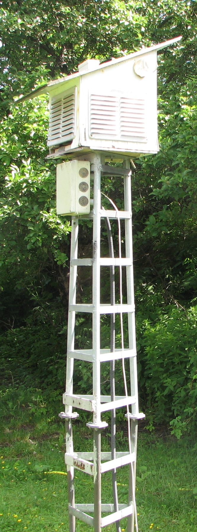
Old Tower before decommissioning
This consists of a stack of plastic flower-decoration pots mounted on top of a 2 meter tall pole, made of 22 mm copper pipe, mounted on a concrete slab.
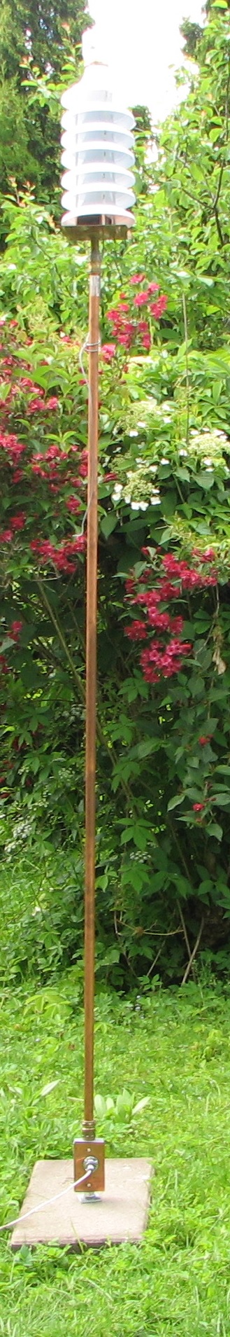
New Tower in place
The top end is a stack of 7 trumpet-shaped pots, originally made for flower displays, but when inverted, with the tip upwards, makes for nice weather-covering for the sensors. The assembly is held together with three M4 brass rods and plastic spacers.
At the top is a glass jar enclosing the light sensors. Below the bottom pot, there is a small black plastic box with the level translator electronics in it. The base is a sheet of copper, where a 1/2 inch pipe stud is affixed, then there is some more plumbing hardware to match this to the 22 mm copper pipe which makes the pole.
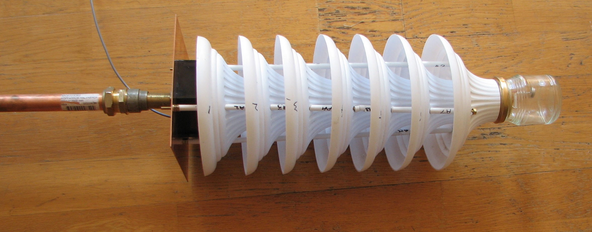
Top end.
The gray cable hanging off the top unit is for input from a switch-type sensor, not yet put to use. This cable has since been shortened and terminated in a BNC bulkhead connector mounted on the copper plate.
At the bottom end, more plumbing parts are used to connect the 22 mm pipe to the 1/2 inch threaded opening at the top of a junction box.
At the bottom of the junction box, there is another connector from 1/2 inch pipe thread to M16 x2 threaded rod, then nuts and washers that holds this firmly mounted to the concrete slab.
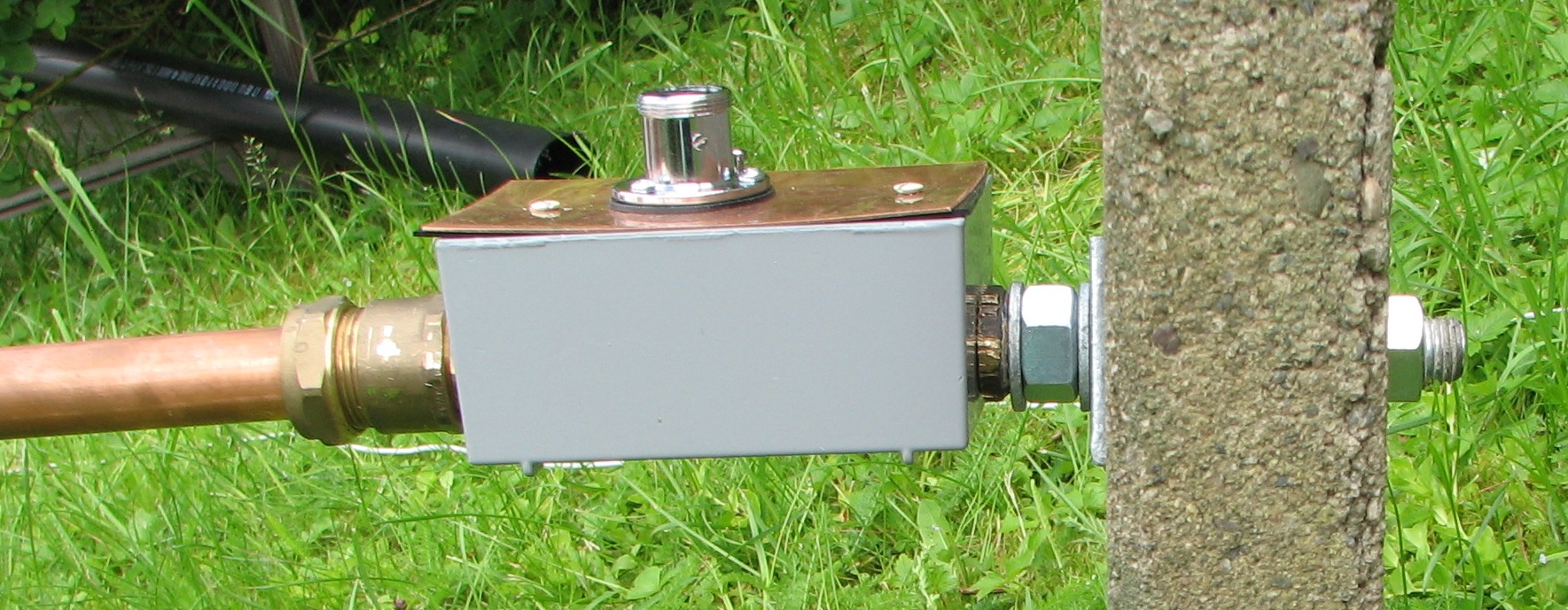
Bottom end showing the connector, the bolt and concrete slab.
There is a minimal amount of electronics in the tower now -- there is a disc of perfboard in the top for the light sensors, and there are two breakout boards mounted at the tips of the second and fourth disks for humidity and pressure both of which also sense the temperature. Then there are the level converter and i2c buffer in the black plastic box below the bottom disc.
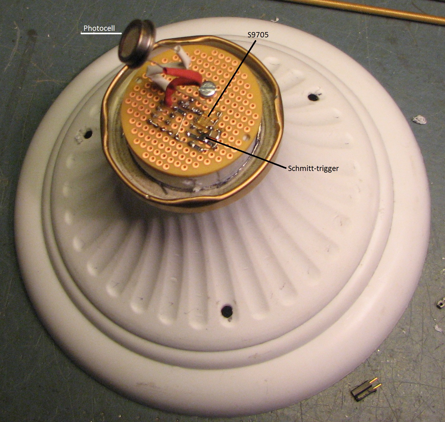
Top disc and perfboard seen from above. S9705, photocell, Schmitt-trigger, and passive components.
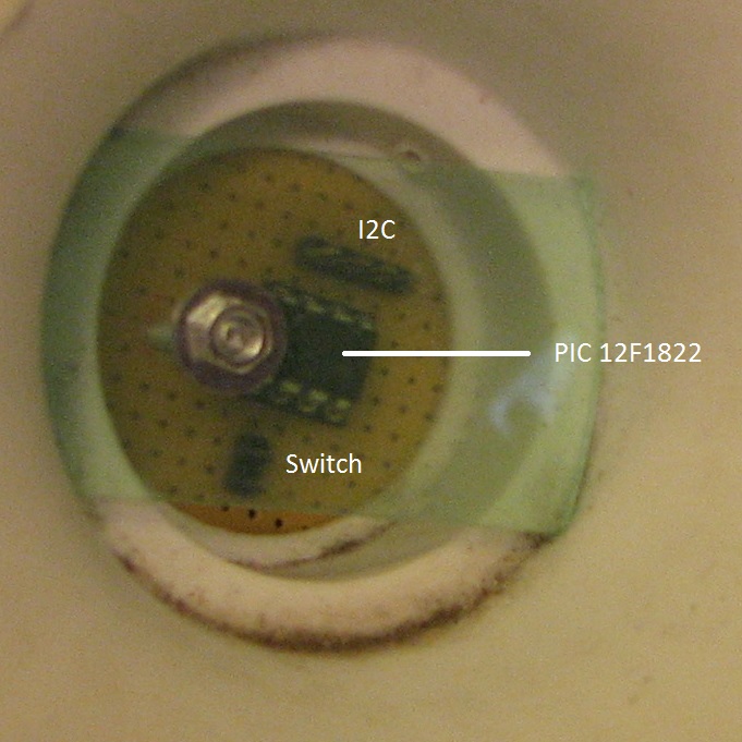
Top disc and perfboard seen from below. PIC12F1822 and the connectors for i2c and switch input.
There are two light sensors, one is an S9705 light-to-frequency chip and the one is a photocell. A PIC12F1822 is programmed to perform the frequency counting and the analog measurement. This also has a counter input which is made available via a Schmitt-trigger through a female BNC connector located at the copper sheet.
Four wires run from the sensors to the level converter forming a short-haul 3.3V i2c bus. At the outside of the level-converter and buffer, 4 wires, in a cable, run a long-haul 5 V i2c bus. This cable is routed inside the supporting pipe.
This cable is terminated in a 4-way marine-style connector mounted to the lid of the junction box at the bottom. Space here is available for adding a ground temperature sensor. This marine connector is the same type and with the same pinout as was used for the data cable on the previous tower electronics.
2017-08: And with the worse problems of corrosion since it is close to the ground. The connector was removed and the cable was connected directly.
There is no longer any need for a separate power cable.
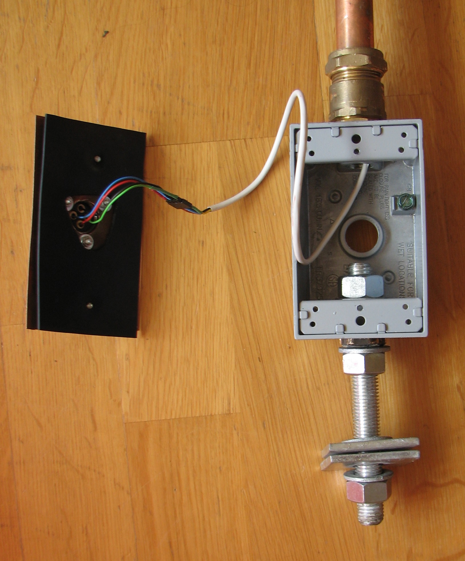
Junction box and inside of the marine connector shows the wires having been routed inside the pipe. This also shows the way the M16 all-thread bolt is anchored inside and outside the box. Green=0V, Red=+5V, Blue=SDA, Black=SCL.
For the tower for temperature and pressure, the base instrument only needs to support a 5V long-haul i2c connection. An interim construction used just that, a Raspberry Pi with a GPIO input for the rainfall pulses as well -- but in order to handle the rain gage heating, a more elaborate unit was made, which includes the 42V transformer.
The following shows the insides of this. The 42V heater connection is made with a Danish standard socket and plug. The advantage of this is that an ordinary mains load such as a heater or lamp could be connected for testing. On the other hand (unless this whole thing were moved to Denmark), it is not possible to insert the plug for the 42V heater circuits into an ordinary 230V outled.
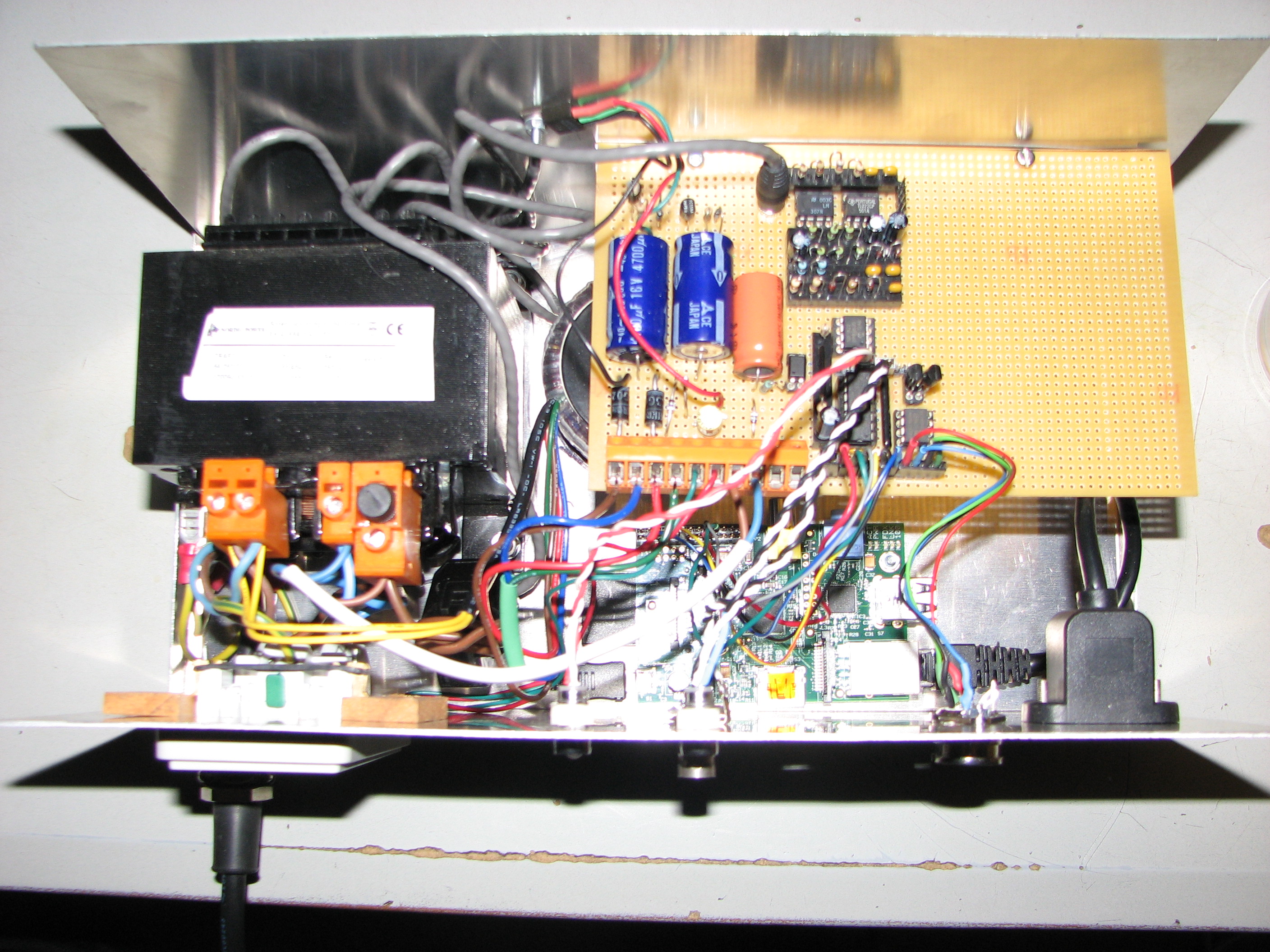
Other connections are BNCs for the rain-pulses input and a spare frequency-measurement channel; a 5-way 240-degree DIN connector for the i2c buss, and the RJ45 for the network. The 42 V transformer is on the left, a toroid for the power supply for the Raspberry Pi computer and the rest of the electronics is partially visible underneath the circuit board. The Raspberry Pi (Model B) is visible at the bottom right.