From 2003-02-13 to 2007-11-16, the external thermometer sensor sat on the outside wall, in a white-painted block of wood. On 2007-11-16, the external, free-standing, "tower", weather station began operating with its first version of electronics. This is a 2 meter tall steel structure carrying a ventilated box, where the air temperature, humidity, light, and rainfall sensors are located. On the ground below the tower is the ground temperature sensor.
The first version, operating from 2007-11-16 to 2008-10-31, used LM35 sensors for the air and ground temperatures, and analog signals on several coaxial cables to the receiving instrument with a multiplexer and ADC0804. This had limitations on cable lengths.
Since 2008-10-31, the temperature sensors have been MCP9801 integrated circuits, connected to the main unit via a long-haul i2c bus. The light and humidity sensors analog-to-digital conversion takes place in electronics on the tower, the ADCs are in a PCF8591, and the rainfall counter is a 4040, read by a PCF8574. The humidity sensor remains the same Honeywell HIH-400(?) as has been throughout.
The temperature errors are attempted minimized by the free-standing design. Heating by the sun on bright days is still evident; the daily curves change depending on cloudiness. The analog electronics in both versions use 1% resistors and low power circuits so as to avoid self-heating. Accuracy of temperature is now limited to what the MCP9081s can provide, accuracy of rainfall is limited by the tipping-spoon design, which tends to under-report rainfall of partial mms -- the water evaporates before it becomes recorded.
The old wall-mounted units would be heated by the sun via the wall, and show too high temperatures. It may be expected that the readings from 2003-2007 are higher; the ones since 2007 should be more accurate.
This is mounted in a box underneath the ventilated box, and two ducts carry cables for the sensors into the box. Inside are the rectifier, voltage regulator, PCF8591 A-D converter, a 4040 counter/PCF8574 combination and op-amps and resistors. There are two marine-style connectors on the back, one is 2-way for the input power, the other is a 4-way one with the i2c bus. A 82B715 is used here for the long-haul connection from the instrument.
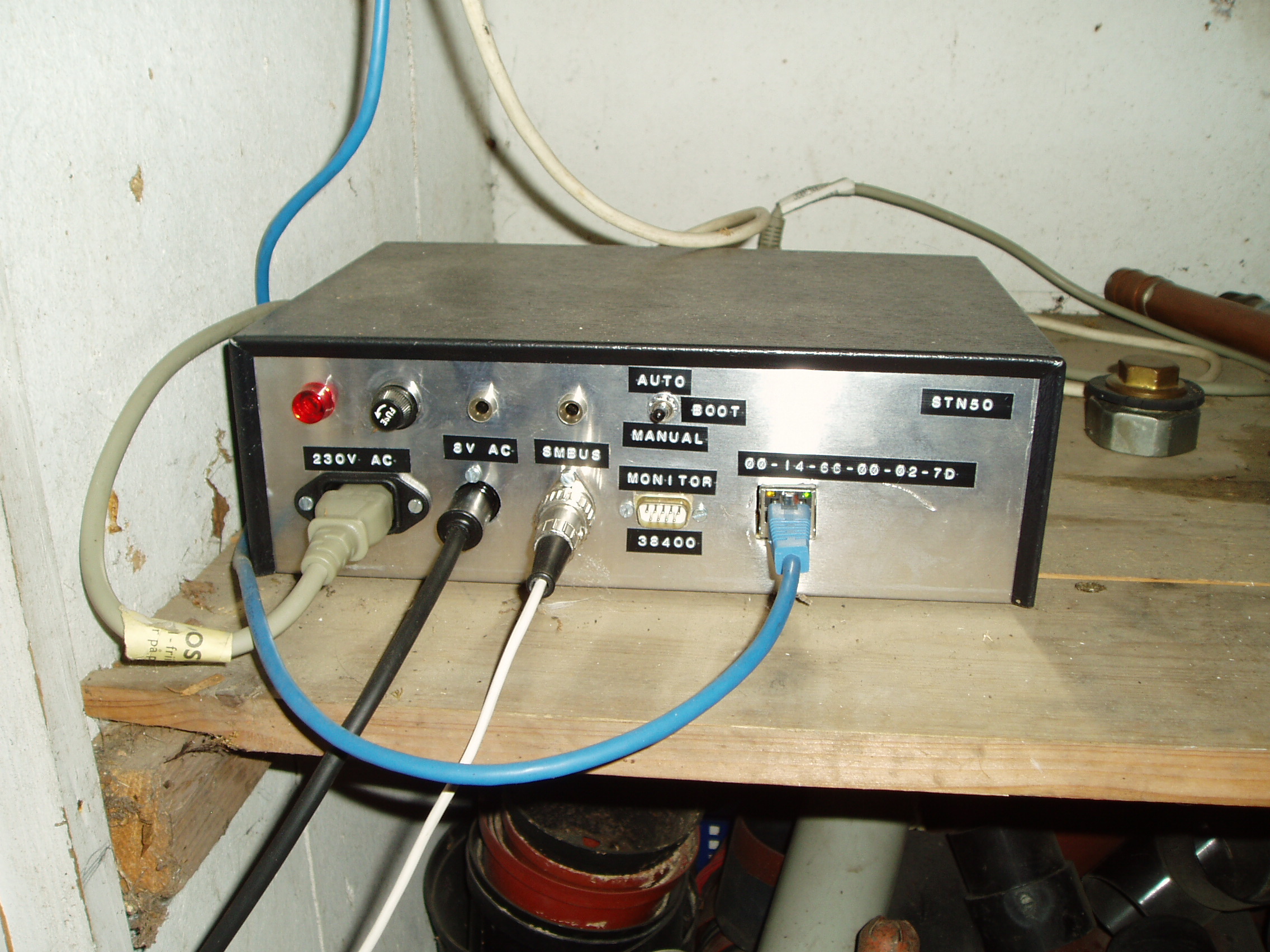
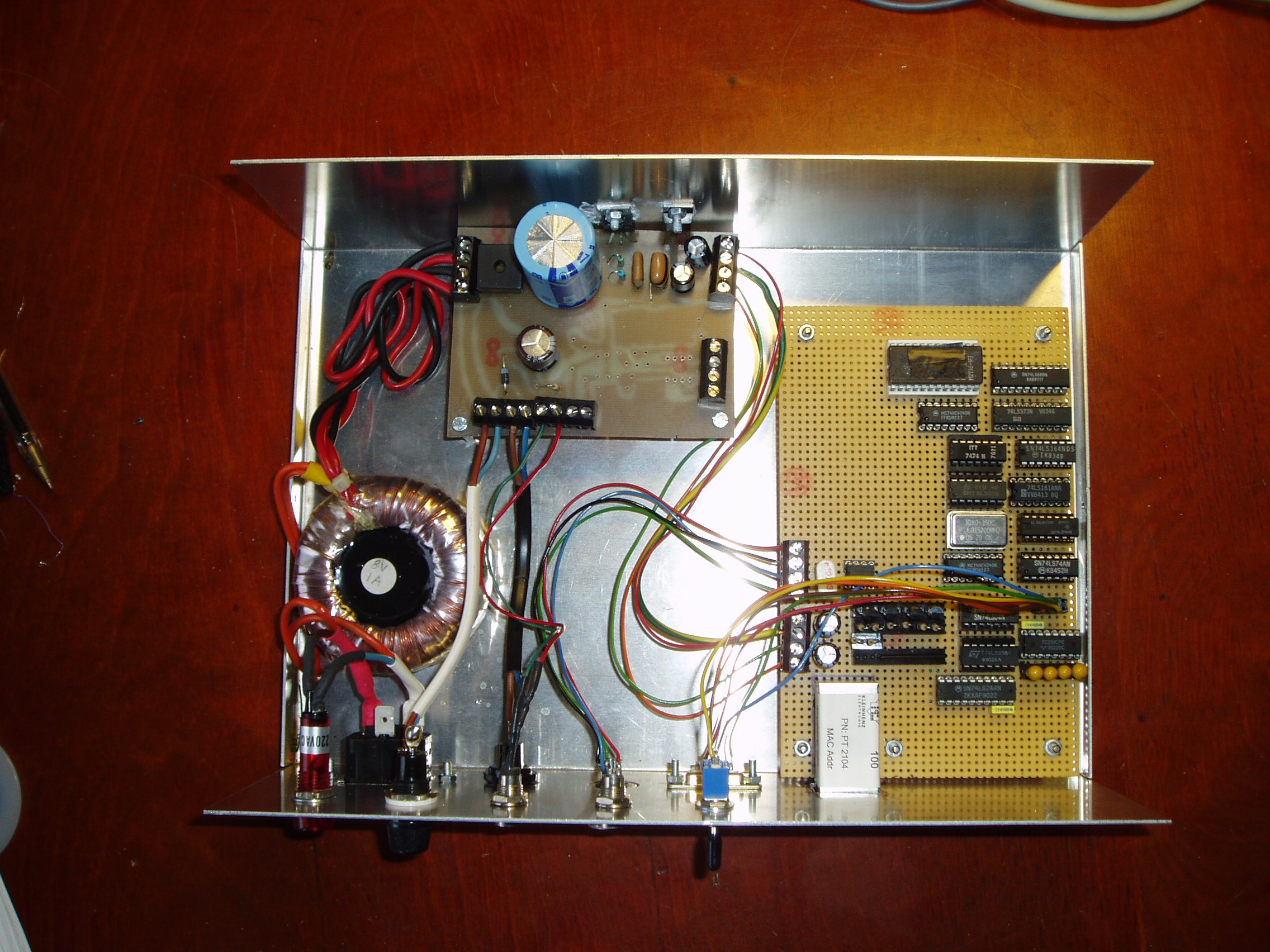
This unit contains the 8V transformer, the Picotux and associated automated start-up circuit, and the 82B715 i2c long-haul buffer circuit for the cable connecting to the tower.
Inside the case are the voltage regulators, the Picotux and associated circuits used to make the system self-starting.
 Details.