I have central heating, with water running in radiators all over the house. This page will tell the tale of how I managed neither to freeze, nor to steam hot, and even how I got the power bills lowered a little.
Once upon a time, there was an analog heat controlling system in this house.
This old system, known as TE-5, would attempt to adjust the position of a mixing valve according to the outside temperature and the time of day. A neat concept, and as it turned out, this used to work OK when it was cold outside during the winter.
Now, occasionally, even here, 59.917 degrees North, the weather becomes mild, and when this happened, the unit couldn't decide on whether to run cold water, all cold and recycled, or hot, all hot fresh from the boiler. Though it was analog, its behavior was two-state, binary, in this kind of weather.
Anyways, this stopped working properly years ago, before I moved back here, I was looking at a nearly 30 years old piece of electronics, which was not exactly on the leading edge in its day either. We're talking germanium transistors and some strange nonlinear battery-like components of mysterious provenance and function.
Since the controller didn't work, the only way was to run the motor for the mixing valve manually
As we can see in the picture, the motor drives the valve through a mechanical linkage. The valve is shown in its middle position here. The outbound water goes out through the iron pipe on the left where we can see the first union joint of it. The orange surface below is the top of the boiler.
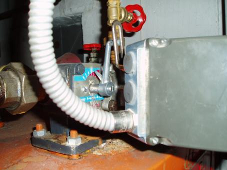
The large box to the right, with the cable emerging from it, contains the motor. Behind the valve, we can see the top of the circulation pump, this is the red cylinder. There are also two bright red valve wheels visible, the one behind the mixing valve, next to the pump, is on the inbound water line. The other one sits on the vertical pipe which goes to the expansion vessel in the attic.
Manual control of the valve, by switching the motor via the still-functioning manual part of the old controller, was easy when I was living in the house all the time. Just go down and turn the heat up or down as it felt necessary.
Then I started working in England. And so I would leave the valve set to some comfortable position, suitable for whatever weather at the time I left, and then it could be anybody's guess what it would be like when I came back.
Would I come back to a big fridge with less than 10 degrees C inside, that took 3 days of the boiler and heating going full blast to get back some decent temperature? Or would I find that the house had turned into a sauna, which would allow me to wear nothing, except maybe shorts just for decency's sake, indoors in the middle of the winter; yet not find it too cold?
I experienced both of these extremes.
Something better than this was needed.
The old system had to come out, and something better would have to come in its stead. It was realized, that the valve-motor was working well, and the plumbing side were OK, so it became a matter of finding out how that motor was controlled.
This turned out to be a matter of switching mains voltages to it. Power it on one set of wires and it would turn towards cold; feed it power on the other set of wires and it would turn towards hot. On reaching either end of its range it would stop and disconnect by itself and not move further in that direction. All in all, a rather nice interface, very amenable to relay control.
Having figured out that, now how to get a decent temperature? How about measuring it inside where it actually counts, as opposed to everywhere else, such as the outside and on the outbound water line? A splendid idea...
So I put together a little unit inside a deep switch box. And placed it in the living room far away from any artificial heat sources and the like. The initial appearance on the wall is simply as a large white box. UK-style, those 1-gang boxes they use there really make useful enclosures, and they don't look all that bad on the wall either.
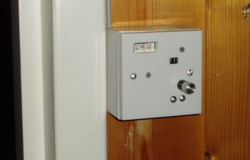
This is the external view. There is a little moving-coil meter indicating actual temperature, a window where the set temperature in degrees, 21 in this picture, is shown, and a knob with which one may set this desired temperature. The unit communicates with the main controller sitting in the boiler room through a 4-core screened cable, which we can see emerging upwards at the top left corner, along the door jamb. The other end of this cable is connected to the main controller in the boiler room.
Here are some more details, an internal view, and a circuit diagram of this unit.
Downstairs in the boiler room is where the main controller is located. It sits on the wall using the case of the old unit, which conveniently terminates all the cables connected to the mixing valve, mains power, and the temperature sensors on the outbound water line and outside.
This picture shows the front panel view.
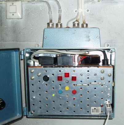
The cable entering on the left, coming from the wall switch, is the mains power. The next cable comes from the old outside sensor, which sits on the north-west wall of the house, and which appears to be a simple temperature-dependent resistor. The third cable is the skinny gray cable connected to the unit in the living room. Here is its other end. The next fat white cable is the one going to the motor, and the last one to the right is coming from a sensor sitting on the outbound water pipe. These two temperature sensors are connected, and some data for them is logged, but that data is not used for anything at present. The outside temperature that is being displayed is measured by other means.
Inside the case, at the top left, we see the plugs for the motor and the input power. Next to this is the motor-movement detection transformer, and behind the transformer we can barely see the two relays. Further to the right is the power transformer for the unit itself, and then the plugs where the various sensors are connected.
The unit chassis is made of two perforated steel plates originally meant for keeping wooden beams together, but their size and shape was perfect for this use as well, as they fit nicely into the old case. The holes also made convenient starting points for the front-side controls.
The front panel shows the main fuse, then three neon lamps indicating motor movement and position. The three pushbuttons below them are for manual motor control, and there are also two LEDs below the blue and the red buttons indicating the relays' positions. The green LED, which appears lit here, indicates proper operation when it flashes one second on then one second off.
The red button forces the valve to go in the warmer direction, and the blue button similarly forces the valve to go in the colder direction. The LEDs below these buttons light up when the corresponding relays are energized.
The yellow button stops the valve motor. As mentioned before, the motor itself also stops when it comes to either end of its movement.
Near the bottom right is the reset button and the serial port which is used for debugging and data logging. The white cable connected here goes to a serial port of a PC which does most of the data logging work.
This unit contains an 8085 microprocessor, an A/D converter with a multiplexer, relays, and some other associated circuitry to turn the relays on and off. Every hour, the unit makes a measurement of the inside temperature as set and actually measured, then decides on movement of the valve motor towards the cold or the warm side.
All the information about the inside temperature and motor movements seen on the thermometer server page comes from this process. The data is recorded by an old 486 PC running Linux, and two processes here cooperate to generate the display. One process records the data coming from the controller, and the other process is a small http server, which emits the latest information on port 9990 when requested, or via the showterm client program run through cgi on the main Apache server.
Another process, which used to be here, but have since been moved to the main webserver, reads the outside temperature through another serial port. Other data-logging processes may at times also be running on this machine.
All these various server programs running on Linux are written in C, whereas the controlling program in the boiler room unit is in 8085 assembly. The outside temperature server also allows other clients in the LAN to call on it to see what the temperature outside is, through the port 9991, which is only used internally.
As previously mentioned, the outside temperature is measured by another, completely separate device. Eventually, I might be able to use the sensor connected to the boiler room unit for this as well, but until then, there is another application for an LM35. This also has the advantage that I can see the temperature on a separate display, so as not having to hit the LAN just for that.
Prior to 2005, the actual sensor sat high on the outside southest wall. On midday, December 31 2004, the sensor was moved to the outside of the northeast wall, close to the northern corner of the house.
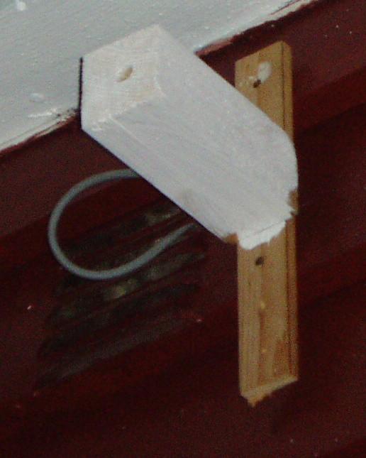
Inside the white-painted 2 by 2 block of wood is an LM35 inside a brass tube, and the cable can be seen going through the ventilation grille.
The wood is painted white in an attempt to avoid heating by the sun. Some heating may still be expected, given the dark red wall and the fact that the roof is sticking out right above. However, this is near the northern corner of the house, so there should not be too many problems with the sunshine.
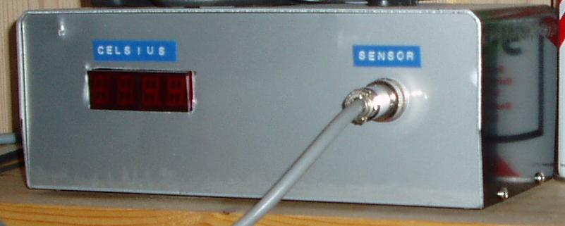
At the other end of the sensor cable is the display-unit. This shows the temperature on a 4-digit LED display and it also has a serial port where the computer can ask it for what the temperature is.
Here are some more details, an internal view, and circuit diagrams of this unit.
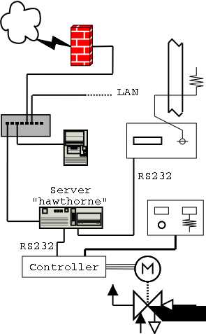
This shows a diagram of the entire set-up.
Since 2007, the external temperature measurements have been performed by a free-standing unit located in the backyard. In addition to air temperature, the temperature on the ground, rainfall, and humidity is recorded. The measurements are done every hour, whenever the thermostat controller decides to check the inside temperature and adjust the valve position, as well as at two set times during the day: at 1118 UT which is solar noon, and at 1200 UT.
More about the weather station prior to 2015-07-31. More about the weather station after 2015-08-01.